Racecar Stuff
Post Ad
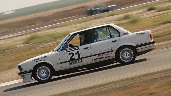
1991 BMW 325is
$20,000
2005 Chevrolet Tahoe
$20,000
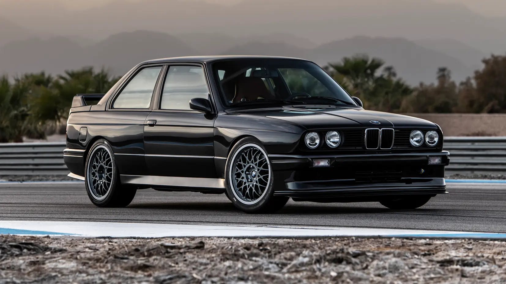
1989 bmw M3
$20,000
2003 Bmw M3
$20,000
2003 Bmw M3
$20,000
2003 Bmw M3
$20,000
2003 Bmw M3
$20,000
2003 Bmw M3
$20,000
2003 Bmw M3
$20,000
2003 Bmw M3
$20,000
2003 Bmw M3
$20,000
2003 Bmw M3
$20,000